The
coaxial cone serves several important functions. In some
ways it does mimic a transmission line with it's ability
to confine or shield radiation from the base of the center
vertical radiator. Because it's tapered, it transforms the
impedance of the antenna so that it can be efficiently
matched to 50 ohm coax. The cone is also tuned to act as
an effective counterpoise and has both transmission mode
and antenna mode currents flowing through it. Transmission
mode currents are confined within the cone and antenna
mode currents are allowed to radiate constructively on the
outside of the cone.
Let's
examine how this principle allows us to simulate a
collinear antenna. Normally the end fed antenna will begin
to radiate from its base in a phase that is
deconstructive once the wavelength is increased
significantly beyond 1/2 wave. Pass this point and the
peak gain begins to shift in favor of an upper 45 degree
lobe where it is wasted. This is why it is essential to
confine the radiation from the lower 1/4 wave section of
the center vertical element. Allowing the longer top
section above the cone to radiate constructively with the
currents on the outside of the cone.
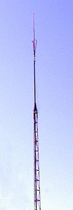
Dominator
NWE-34 radiation currents displayed
in CST model pictured on left.
Advancements
in computer antenna modeling software have made it easier
to understand how the Dominator NWE-34 produces more gain
then any single other commercially manufactured FM
broadcast antenna. CST Microwave Studio is an
exceptionally accurate software tool that provides 3D
Electro-Magnetic simulation of antennas. The image
displays both the magnitude and phase of all radiation
currents along the antenna at a driven phase angle that
produces maximum current. Clicking on the image above and
to the left will
open a GIF video that shows the currents at all driven
phase angles throughout the 360 degree RF sinewave.
Magnitude
is displayed with color intensity and referenced to the
chart on the right. This chart shows the magnitude in amps
per meter for the corresponding colors. Phase is also
indicated by opposing colors at the positive top and
negative bottom of the chart. The Dominator has obvious
characteristics not typically found in antennas other then
collinear types. It has 3 separate radiation currents with
two allowed to radiate freely in a phase that is
constructively combined in the far field. The third
current is in a deconstructive phase with respect to the
other two and has been confined within the tapered coaxial
skeleton cone.
It
is the tapered 1/4 wave coaxial cone that sets this
antenna apart from others. It allows the longer top
section of the main radiator to radiate freely while the
deconstructively phased radiation on the lower 1/4 wave of
the main radiator is confined within the cone. Since the
base of the cone and the base of the main radiator are
excited by opposite phase polarities, the currents allowed
to radiate on the outside of the shielding cone combine
constructively with the longer main radiator extending
above the cone. Total currents radiated by the cone are
divided into its four vertically tapered radials. This
provides noticeable gain over a dipole on the distant
horizon.
Understanding the Cartesian
radiation elevation charts.
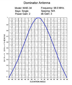

Now
that we have covered how the CST model reveals radiation
currents from the tapered coaxial cone and upper main
radiator constructively combine together, lets look at how
this compresses the Dominators beamwidth in the far field
to produce it's 3 db gain over the dipole. The Cartesian
charts show the normalized field in relation to the
elevation angle above and below 0 degrees horizontal.
Normalized field is the technical term for the relative
amount of field power density the particular antenna can
produce at the given elevation angle, with 1 being equal
to 100% of its maximum radiated RF field. Clicking on
either image above will open a larger version.
The
half wave dipole shown in red has a broader less
compressed slope then the Dominator shown in blue. This
wastes power by radiating it well above and below the
horizontal plane. The dipole is still radiating 50% of
it's maximum field at an angle that is -60 degrees from
horizontal. In comparison, the Dominator field is reduced
to 50% at an angle of -47 degrees from horizontal and it's
down to 33% at -60 degrees. Effectively refocusing the
power wasted at undesired angles into a tighter beamwidth
that is 3 db stronger then a dipole at the critical 0
degree elevation angle.
Because
the Normalized fields are relative to the specific
antennas full power field, it is not apparent how the
beamwidth effects the two antennas Effective Radiated
Power in comparison to each other. We only see the
percentage of the individual antennas full field at any
given angle. If we were to lay the dipole chart over the
Dominator chart and used the Dominators Normalized Field
as the reference point for peak field power, the
differences would be clear.
The
peak field for the dipole would only reach approximately
0.75 or 75% of the Dominators peak Normalized field.
Placing it 3 db lower as a result of wasted energy at
angles that are not useful to VHF broadcast propagation.
The Dominators compressed beamwidth not only increases
gain, it reduces on site RF exposure levels with limited
downward radiation making it easier to comply with safety
standards.
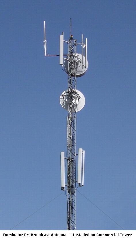
The
Dominator® antenna was developed for FM Broadcast in 1996
by Norwalk Electronics. It is a high gain vertically
polarized .82 wave Coaxial antenna. It is the coaxial cone
at the base of this antenna that allows us to go beyond
the standard 1/2 wave and 5/8 wave designs while forcing
the angle of radiation down on the horizon. The Dominator®
has the same vertical gain as four stacked circular
polarized bays fed in phase and mounted over a forty foot
section of tower.
This
antenna uses a highly efficient Teflon insulated gamma
match that eliminates any coils or matching transformers.
That enables shunt feeding of the .82 wave main radiator,
keeping it DC grounded for added lightning protection.
This also gives the antenna it's ability to handle high
power levels. The standard model is available with a gold
pin Teflon insulated weatherproof N or SO-239 connector
recommended for up to 1 KW input. Higher power versions
are also available such as our 3 kilowatt using a Teflon
7/16" DIN connector and heavy duty gamma match.
Beware
of poorly constructed clones that look similar to the
Dominator®. One distributor in Slovenia is selling an
antenna that has been made to look like the factory
authorized product . Clones are not factory authorized and
are advertised with inflated gain figures. Please visit
our "Dominator vs. Clone" page for more
information. Norwalk Electronics guarantees no single
other FM broadcast antenna can produce a stronger signal
or you can return the antenna to us within 30 days for a
refund.
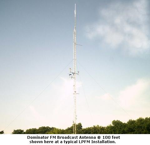
The Dominator® is
professionally manufactured using high grade 6063
magnesium alloy aluminum tubing. This antenna is currently
in use by hundreds of stations around the globe from
Alaska to South America. It has proved itself to withstand
severe weather while providing a strong reliable signal.
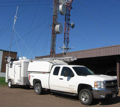
The Dominator® also offers
unique possibilities for use in emergency or temporary
situations where an effective, easy to install antenna is
required. Be prepared for the unexpected as changes in
weather patterns can cause a severe weather system to
strike at anytime. This has forced some stations into the
awkward position of having to reach their listeners after
the loss of the transmitter antenna and or tower.
 All
antennas on our website are backed by our
All
antennas on our website are backed by our
30
Day Money Back Guarantee
and
for a limited time only
FREE SHIPPING
in
the United States!
Guaranteed to out perform any single antenna
currently available on the market!
|
Gain:
6 db
|
| Length:
9 feet |
|
Impedance:
50 ohms
|
| Polarization:
Vertical |
| Wavelength:
.82 wave |
| Weight:
Approx. 7 to
8 pounds |
| Wind
load: .7 square feet |
| Max.
wind speed: 100 MPH |
| Bandwidth:
5 MHz @ <1.5:1 |
| VSWR:
1:1 at tuned frequency |
| Frequency
range: 88-110 MHz. (Tunable) |
| Material:
High grade 6063 alloy aluminum |
| Connector:
N
or SO-239 (7/16"
DIN for 3 KW.) |
| Radiation
pattern: Low angle omni (14
degrees) |
| Lightning
protection: DC grounded
radiator |
| Maximum
Power: 1 Kilowatt.
(3 KW high power) |

Be
sure to check out the latest specials and discounts on our specials page!
|
|
|
1KW
Model $349.00
|
3KW
Model $459.00 |